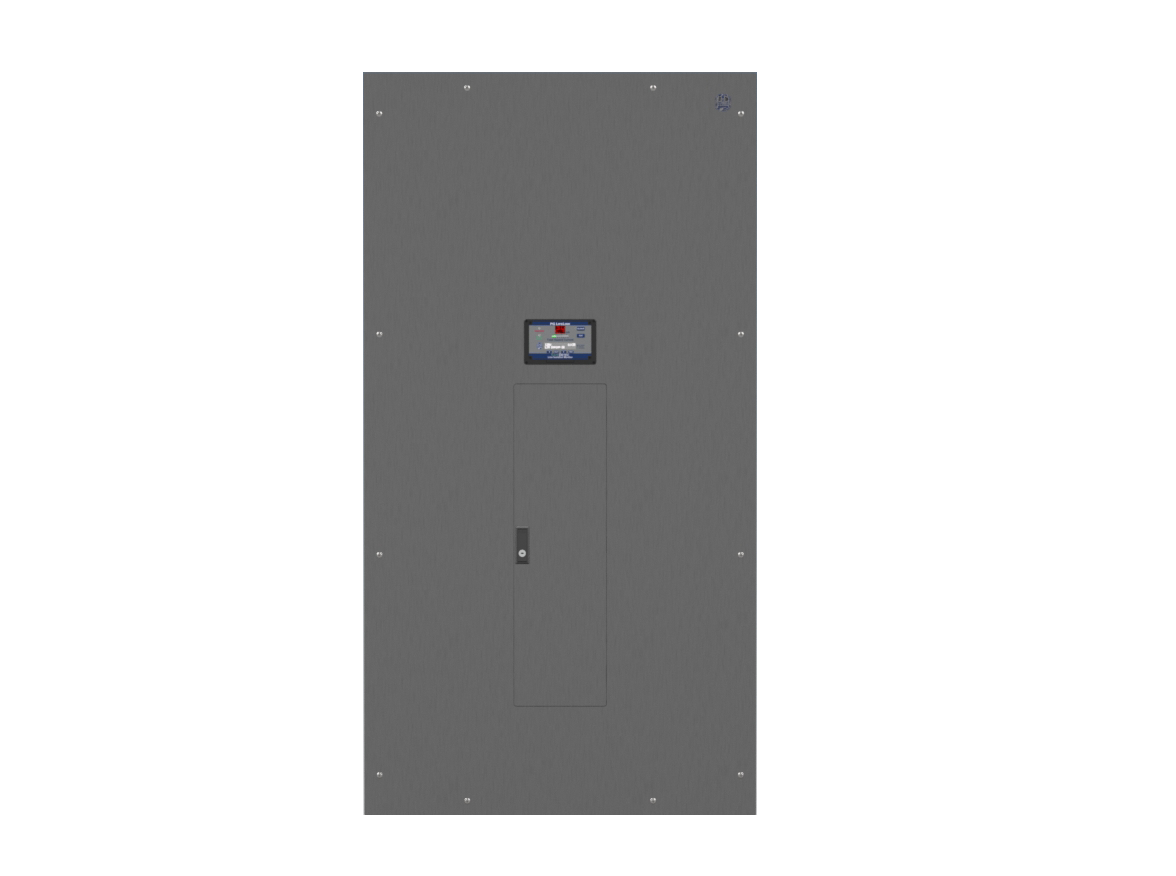
The Laser Isolated IPL Power Panel model is a Laser Isolated Power Panel that includes a concealed hinged front and is designed to supply power to remote Laser Outlet Modules located in multiple procedure rooms from a single, centrally located panel. This panel is typically installed in a hospital operating room or other procedure room designated for laser procedures. This Remote Medical Power Outlet is a cost-effective way to provide high voltage output to multiple locations from a single panel.
The Laser Isolated IPL Power Panel is the industry standard for high density OR areas that require maximum flexibility when scheduling laser procedures.This centrally located system intelligently and efficiently distributes 208-240V isolated power on-demand to compact Laser Outlet Modules in multipleprocedure rooms
Included with panel
- Dedicated 208-240V isolated circuits to multiple ORs from a central panel
- Available in 15 or 25 kVA capacity with up to 12 branch circuits
- Up to 12 208 or 240V, 30 or 50A circuits for cord-connected, portable laser device loads
- Laser Outlet Modules, including NEMA receptacle and LIM remote, are installed inside each OR
- PLC-based “Plug-Control” system automatically limits the number of energized circuits to minimize leakage current and avoid accidental shutdown
Standard configuration includes a Programmable Logic Controller (PLC) system. This system protects against accidental overload and allows power to be selectively provided to the location needed. The outlet is energized by opening the receptacle cover, activating the contact switch, and signaling the panel PLC to power the circuit. Once energized, the circuit is locked on until the device is disconnected and the cover is closed. The lockout feature can also limit the number of energized outlets, allowing the hospital to control the number of lasers and/or X-ray procedures performed at any one time.
Up to 12 outlets can be connected to the Plus Series IPL-P Panel. The number of energized outlets operated simultaneously is determined by the transformer capacity and the distance of outlet locations from the panel. The PLC protects against overloading the panel transformer. For more information on our remote medical power outlet, see design recommendations here.
Panel Sizing
|
kVA Size Options |
Back Box Size |
| 15 |
70"H x 36"W x 12"D
|
|
25 |
Features
All Plus Series IPL-P Isolated Power Supply Systems include:
Hospital Grade Isolation Transformer:
- Supplies up to 12 each (208 or 240V, 30 or 50A) circuits for cord-connected, portable laser device loads
- Standard sizes for each section range from 15 to 25kVA for portable laser devices
- Primary voltages: 480, 277, 240, 208, and 120* VAC
- Secondary voltages: 240, 208, and 120** VAC
- Low leakage, electrostatically shielded primary and secondary windings
- 220°C Class R Insulation
- Clamped and bolted design with anti-vibration mounting bushings for quiet operation
- Designed and built in accordance with UL and CSA Standards
- 50Hz available (optional)
*120V primary not available for IPD and IPL panels
**120V secondary not available for IPL panels
SafeDetec Line Isolation Monitor (LIM):
- State-of-the-art all digital Total Hazard Current measurement
- Advanved filtering and noise suppression for improved accuracy and reliability
- High contrast 40-character LED display for better visibility and viewing angle
- Universal 120-240 VAC power input allows LIMs to be directly Interchanged from 120V to 208V/240V laser panels without changing the internal jumper or switch settings
- Additional parameters can be displayed on the user interface for more advanced troubleshooting, such as L1 and L2 line-to-ground voltages, insulation resistance, and insulation capacitance
- Increased memory allows more log entries and a longer history of LIM data
Interior Chassis
- Interior chassis built to order, fully assembled in the factory, and 100% tested
- Primary main circuit breaker
- Up to 12 factory installed 120V, two-pole, bolt-on branch circuit breakers*
- Copper ground bus
- Terminal strip for connecting Remote Annunciator(s)
- Customer may specify standard circuit breakers from Eaton, GE, Siemens, or Schneider Electric for consistent coordination or to maintain facility standard*
Enclosure and Trim:
- Heavy-duty galvanized steel back box designed for flush mounting; can be shipped ahead of interior during rough-in
- Stainless steel front trim panel with fully hidden hinged, door-in-door construction reduces damage and potential injuries during installation, testing, and maintenance*
- Surface mounting options available
Available Accessory Outlet:
- At least one Laser Outlet Module is required for each branch circuit supplied by an XTL panel.
- Laser Outlet Modules include a user-specified NEMA receptacle, LIM Remote Annunciator, galvanized back box, and a stainless steel front trim with hinged door over the laser receptacle
- Standard configuration includes a Programmable Logic Controller (PLC) system.
- Optional non-controlled version available
- Optional “In-Use” light controls available
- Find more information on the Laser Outlet Module page
Installation
- Special low leakage wire should always be used for the powered conductors of branch circuit wiring. XPLE type insulation such as XHHW-2 wire is recommended with a dielectric constant of less than 3.5. Standard type insulation such as THHN is appropriate for the incoming primary and the ground wires only.
- The NEC (Article 517.160) requires secondary circuits to be colored brown and orange, with a distinctive stripe in a contrasting color. The brown wire is connected to the L2 bus and the hot side (brass screw) of a standard NEMA receptacle. The orange wire, L1 is connected to the silver screw where neutral would be connected. Polarity should be maintained throughout the installation.
- Conduit runs for branch circuits should be as short and direct as possible to minimize accumulated leakage current in the circuit conductors. Generally, 400‐450 feet is the maximum recommended cumulative length for all branch conductors from a single transformer. Avoid unnecessary bends and junctions.
- Do not use pulling compounds to lubricate inside of conduit. This will break down the insulation properties and raise leakage current. A dry talc powder may be used. It is typical to use conduit with a slightly larger diameter to ease pulling and avoid damage to wire insulation. An interior coating of PVC may also be used.
- Isolated power circuits must be kept separate from other circuits. Do not share conduit or raceway with non‐isolated circuits, or isolated circuits from another system.
- Each receptacle and equipment grounding connector must be connected back to Reference Ground Bus inside Isolation Panel to maintain Equipotential grounding system. If multiple panels serve the same space, they must be bonded together.
Certifications
PG LifeLink Isolated Power equipment is designed, built, and tested in accordance with the following:
- UL 1047, UL 1022, UL 50
- CSA C22.1 Part 1, and CSA C22.2 No. 204
- IBC (2012), AC156 (2010), ASCE 7-10
- OSHPD (State of California), OSP-0210-10
PG LifeLink Plus Isolated Power Systems UL Certification document
PG LifeLink Isolated Power Panel IBC 2018 Seismic Certification - For more information, click here.
*Only PG LifeLink offers this as standard
or Contact Us at 800.287.4123